I've been using Eclipse with Segger's JLink for a while now to write my FreeRTOS applications. It's all good, until you want to check the state of threads. When you pause execution in debug mode, what you'll see most likely is idle thread. Because that's what embedded systems do for most of the time - they idle. Often when some task dies or hangs, everything else is still working. At least idle task is working. Unless the system experiences hardfault.
So I finally decided to improve my debugging facilities to obtain at least some info on the state of the system. I'll document my findings as I figure things out. This one will be about threads.
Showing posts with label FreeRTOS. Show all posts
Showing posts with label FreeRTOS. Show all posts
FreeRTOS and Semihosting issues
Semihosting is a way of providing missing I/O resources to the development platform. Most popular use of it is as debug output console using standard printf(). Turns out, there are some certain limitations to it.
STM32 + HAL + FreeRTOS Part III: SPI (blocking)
Serial Peripheral Interface (SPI) is quite widely used in embedded systems for connecting all kinds of ICs - sensors, memories, screens, you name it. It seems to be somewhat less popular among the beginners/Arduino crowd than I2C, because of relatively more complicated setup. But it does provide higher speeds and possibility to have more of the same type sensors on a single bus without addressing issues.
STM32F429I-Discovery board has an L3GD20 3-axis gyroscope onboard connected to SPI channel 5. In this article we'll try to get it up and running. I will continue where we left off last time - a working example with blinking LEDs and UART.
So, let us look at the devkit connections, as defined in Discovery board documentation:
In addition to that, NCS_MEMS_SPI has been defined. That would be our CS. And last bunch are interrupt pins. Neat.
Another thing we should worry about (it's a pretty common source of headache) are SPI bus setup. Generated setup in spi.c states:
Let's review it and compare to the data in datasheet. Sadly, they don't just tell you mode SPI is working in, so you have to read the signal time chart and figure it out on your own:
What is happening here, is:
All that's remaining, is just starting the task and let it run. I will add a new handle and reduce the priorities of blinky tasks to avoid them interrupting our transmit, since it is in blocking mode, that might mess things up:
And voila:
 As expected, we get our notification, that system is up. First goes high-priority SPI task and then it continues with low priority blinking. The printout shows, that MCU sent 0x8F to the gyro and got back it's chip identification byte 0xD4, just as expected.
I'm not particularly interested in implementing full driver for the gyro, that can be left as an exercise for the reader. There should be plenty of those already available online.
As usual, sources on GitHub have been updated to include all of the above. Next up: Part V: SPI with DMA
STM32F429I-Discovery board has an L3GD20 3-axis gyroscope onboard connected to SPI channel 5. In this article we'll try to get it up and running. I will continue where we left off last time - a working example with blinking LEDs and UART.
So, let us look at the devkit connections, as defined in Discovery board documentation:
- MOSI is on PF9
- MISO is on PF8
- SCK is on PF7
- Chip-select (CS) is in PC1
- Interrupt 1 is on PA1
- Interrupt 2 is on PA2
#define SPI5_SCK_Pin GPIO_PIN_7
#define SPI5_SCK_GPIO_Port GPIOF
#define SPI5_MISO_Pin GPIO_PIN_8
#define SPI5_MISO_GPIO_Port GPIOF
#define SPI5_MOSI_Pin GPIO_PIN_9
#define SPI5_MOSI_GPIO_Port GPIOF
..
#define NCS_MEMS_SPI_Pin GPIO_PIN_1
#define NCS_MEMS_SPI_GPIO_Port GPIOC
..
#define MEMS_INT1_Pin GPIO_PIN_1
#define MEMS_INT1_GPIO_Port GPIOA
#define MEMS_INT2_Pin GPIO_PIN_2
#define MEMS_INT2_GPIO_Port GPIOA
Another thing we should worry about (it's a pretty common source of headache) are SPI bus setup. Generated setup in spi.c states:
  hspi5.Instance = SPI5;
  hspi5.Init.Mode = SPI_MODE_MASTER;
  hspi5.Init.Direction = SPI_DIRECTION_2LINES;
  hspi5.Init.DataSize = SPI_DATASIZE_8BIT;
  hspi5.Init.CLKPolarity = SPI_POLARITY_HIGH;
  hspi5.Init.CLKPhase = SPI_PHASE_2EDGE;
  hspi5.Init.NSS = SPI_NSS_SOFT;
  hspi5.Init.BaudRatePrescaler = SPI_BAUDRATEPRESCALER_16;
  hspi5.Init.FirstBit = SPI_FIRSTBIT_MSB;
  hspi5.Init.TIMode = SPI_TIMODE_DISABLE;
- Instance: SPI5 is what we want, yes
- Mode: Master mode - we will be initiating the communications
- Direction: 2 Lines. That's what we have and want. Apparently, there's a support for single-wire half-duplex comms as well, but that's not for us
- Datasize: 8bit. True. All the registers are 8bit, wider words are sent as pairs of high/low bytes
- Clock polarity (CPOL): Idle state is high, so polarity is high
- Clock phase (CPHA): Sampling seems to be done on the trailing edge, so this should be SPI_PHASE_2EDGE
- NSS (Slave select) will be done in software for now, by manually pulling CS pin low before transfer, with subsequent pull back up once transfer is done. It is possible to use hardware NSS, but it requires disabling the SPI master after transfer to pull it back up (just an implementation in STM32 HAL)
- Baud Rate Prescaler is a clock divider, which sets the transfer speed. Leave it be for now
- First Bit should be the most significant bit (MSB) as per gyro datasheet
- We are not interested in TI mode for now, so leave it disabled
void vGyroTesterTask(void const * argument) {
 HAL_StatusTypeDef response = HAL_ERROR; // default to error
// 0x0F is WHO_AM_I register, 0x80 read bit, should return 0b11010100 or 0xD4
 uint8_t txbuf[3] = {0x0F | 0x80, 0x00};
 uint8_t rxbuf[3] = {0x00, 0x00};

 HAL_GPIO_WritePin(NCS_MEMS_SPI_GPIO_Port, NCS_MEMS_SPI_Pin, GPIO_PIN_RESET);
 response = HAL_SPI_TransmitReceive(&hspi5, txbuf, rxbuf, 2, 1000);
 HAL_GPIO_WritePin(NCS_MEMS_SPI_GPIO_Port, NCS_MEMS_SPI_Pin, GPIO_PIN_SET);
 if (response == HAL_OK) {
  printf("Sent: %02x %02x Got: %02x %02x\r\n", txbuf[0], txbuf[1], rxbuf[0], rxbuf[1]);
 } else {
  printf("Got error response as %d\r\n", response);
 }
 osThreadTerminate(gyroTaskHandle);
}
- We define default response as error, just to be sure, that it gets changed to HAL_OK
- define a 2 byte wide transmit buffer (with last spot as NULL terminator) First is the byte (command) we send. We want to read (0x80) register 0x0F, then we send bunch of zeros as a dummy payload to give chance to the chip to respond.
- define a 2 byte wide receive buffer (with last spot as NULL terminator). First byte is dummy receive, normally filled with 0xFF (no data), the second one will contain the response from the chip
- pull down our CS pin, to indicate to the slave, that we are talking to it
- Do the actual transceiving of the data
- pull back up the CS pin, to tell the chip, that we are done with it
- check the response status code and print out the data or code received
- kill the thread, for we are done with it
All that's remaining, is just starting the task and let it run. I will add a new handle and reduce the priorities of blinky tasks to avoid them interrupting our transmit, since it is in blocking mode, that might mess things up:
osThreadId defaultTaskHandle, blinkyTaskHandle, gyroTaskHandle;

..

void MX_FREERTOS_Init(void) {

 osThreadDef(defaultTask, StartDefaultTask, osPriorityLow, 0, 1000);
 defaultTaskHandle = osThreadCreate(osThread(defaultTask), NULL);

 osThreadDef(blinkyTask, vBlinkyTask, osPriorityLow, 0, 1000);
 blinkyTaskHandle = osThreadCreate(osThread(blinkyTask), NULL);

 osThreadDef(gyroTask, vGyroTesterTask, osPriorityHigh, 0, 1000);
 gyroTaskHandle = osThreadCreate(osThread(gyroTask), NULL);
}
I'm not particularly interested in implementing full driver for the gyro, that can be left as an exercise for the reader. There should be plenty of those already available online.
As usual, sources on GitHub have been updated to include all of the above. Next up: Part V: SPI with DMA
STM32 + HAL + FreeRTOS Part II: UART
Previously we started a blinky project on STM32F429-Discovery board with HAL and FreeRTOS. I will continue to build up on it with Universal Asynchronous Receiver-Transmitter or UART.
If you remember well, during code generation, I instructed to leave USART1 in the list of peripherals to initialize in generated code. This was done so that we wouldn't have to figure out how to initialize it and provide it with clocks manually.
So STM32CubeMx generated usart.c/.h files for us, which contain USART1 initialization function, which defines UART parameters and two functions, which HAL expects user code to implement - HAL_UART_MspInit() and HAL_UART_MspDeInit() for setting up and teardown of hardware resources required for peripheral.
With this setup, UART should already be working and you could try to transmit data by using HAL_UART_Transmit(&huart1, &charbuffer, size, timeout):
But most of the time we don't want to deal with bytes and buffers, we want a convenient printf() function, which does all the formatting for us. So what we have to do, is called retargeting printf(). Meaning, that we tell it to send to USART1 as a default console. To accomplish that, all we have to do is (re)implement __io_putchar() and _write() functions:
We shall call it printf_retarget.c. We'll make a companion header file, where we'll add include guards and prototypes:
For this bit of code to be used, we have to include it after usart.c in C_SOURCES definition in the Makefile and in main.c we can replace '#include "usart.h"' with '#include "printf_retarget.h"', for usart.h becomes a nested include.
And now we can use printf() function to our own pleasure. Let us add some output to the startup sequence:
and to our task as well, so it would inform us, that it is turning the LED on:
Now, if we connect USART to our PC (I use FTDI232 for that. STM32 I/O pins are 5V tolerant, meaning that the serial converter does not necessarily have to be running in 3V3 mode) by connecting pins PA09 RX to PC TX, PA10 TX to PC RX, we can get our printouts:
The serial port settings are defined in usart.c:
Next up: Part III: SPI in blocking mode
If you remember well, during code generation, I instructed to leave USART1 in the list of peripherals to initialize in generated code. This was done so that we wouldn't have to figure out how to initialize it and provide it with clocks manually.
So STM32CubeMx generated usart.c/.h files for us, which contain USART1 initialization function, which defines UART parameters and two functions, which HAL expects user code to implement - HAL_UART_MspInit() and HAL_UART_MspDeInit() for setting up and teardown of hardware resources required for peripheral.
With this setup, UART should already be working and you could try to transmit data by using HAL_UART_Transmit(&huart1, &charbuffer, size, timeout):
HAL_UART_Transmit(&huart1, &charbuffer, size, timeout)
But most of the time we don't want to deal with bytes and buffers, we want a convenient printf() function, which does all the formatting for us. So what we have to do, is called retargeting printf(). Meaning, that we tell it to send to USART1 as a default console. To accomplish that, all we have to do is (re)implement __io_putchar() and _write() functions:
#include "usart.h"

/* (Re)Define stdio functionality, so printf would output to USART1 */
int __io_putchar(int ch) {
 uint8_t c[1];
 c[0] = ch & 0x00FF;
 HAL_UART_Transmit(&huart1, &c[0], 1, 10);
 return ch;
}

int _write(int file,char *ptr, int len) {
 int DataIdx;
 for(DataIdx= 0; DataIdx< len; DataIdx++) {
  __io_putchar(*ptr++);
 }
 return len;
}
We shall call it printf_retarget.c. We'll make a companion header file, where we'll add include guards and prototypes:
#ifndef INC_PRINTF_RETARGET_H_

int __io_putchar(int ch);
int _write(int file,char *ptr, int len);

#define INC_PRINTF_RETARGET_H_

#endif /* INC_PRINTF_RETARGET_H_ */
For this bit of code to be used, we have to include it after usart.c in C_SOURCES definition in the Makefile and in main.c we can replace '#include "usart.h"' with '#include "printf_retarget.h"', for usart.h becomes a nested include.
And now we can use printf() function to our own pleasure. Let us add some output to the startup sequence:
..
  MX_USART1_UART_Init();

  printf("System configured!\r\n");

  /* Call init function for freertos objects (in freertos.c) */
  MX_FREERTOS_Init();
..
and to our task as well, so it would inform us, that it is turning the LED on:
void StartDefaultTask(void const * argument) {

  for(;;) {
   osDelay(500);
   HAL_GPIO_TogglePin(GPIOG, GPIO_PIN_14);
   if(HAL_GPIO_ReadPin(GPIOG, GPIO_PIN_13) == GPIO_PIN_RESET) {
    printf("Blink!\r\n");
   }
  }
}
Now, if we connect USART to our PC (I use FTDI232 for that. STM32 I/O pins are 5V tolerant, meaning that the serial converter does not necessarily have to be running in 3V3 mode) by connecting pins PA09 RX to PC TX, PA10 TX to PC RX, we can get our printouts:
 |
| It speaks! |
The serial port settings are defined in usart.c:
- 115200 baud
- 8bit word length, 1 stop bit
- Parity: none
- Hardware control: none
Next up: Part III: SPI in blocking mode
STM32 + HAL + FreeRTOS Part I: Setup (blinky)
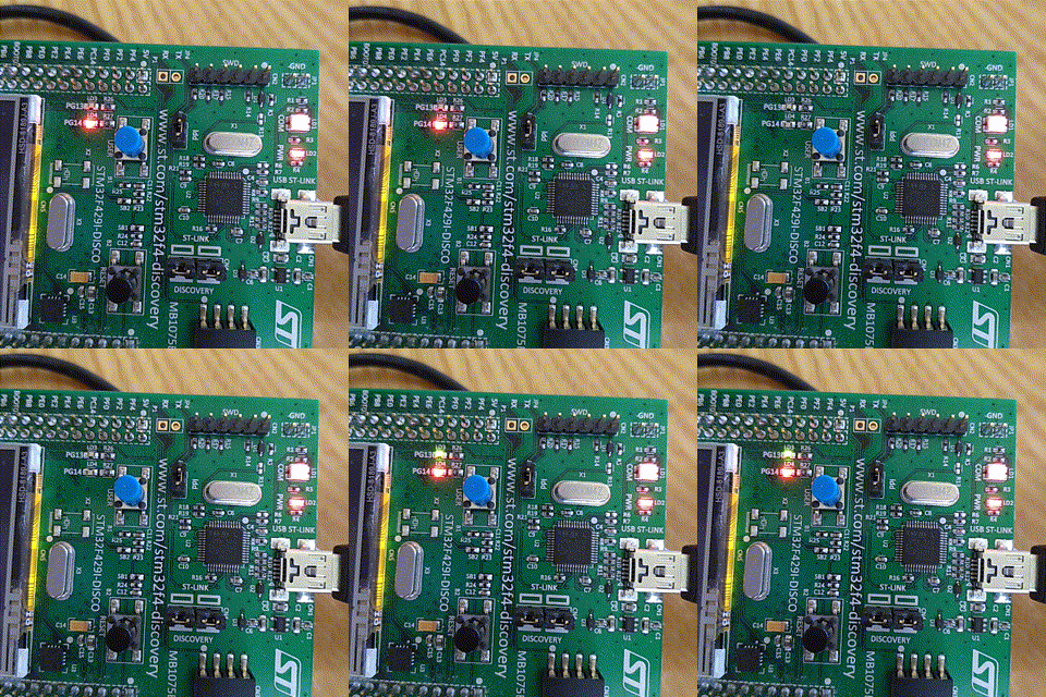 |
| It's alive! |
For as much as it is reasonable, I prefer to use free tools in my development work. That includes compilers, IDEs and even OS. So the software setup will be geared towards Linux, but with minimal changes should be working also under windos/mac.
First thing we need is a compiler. I will use GNU Arm Embedded Toolchain. Setup is pretty simple - unpack it and leave it be. I'll unpack it into "tools" directory in user home (~/tools). At the time of writing this, latest version is 7-2017-q4-major, so final location of toolchain is "~/tools/gcc-arm-none-eabi-7-2017-q4-major". You can test it by calling arm-none-eabi-gcc with version parameter and it should print version info:
~/tools/gcc-arm-none-eabi-7-2017-q4-major/bin$ ./arm-none-eabi-gcc --version
arm-none-eabi-gcc (GNU Tools for Arm Embedded Processors 7-2017-q4-major) 7.2.1 20170904 (release) [ARM/embedded-7-branch revision 255204]
Copyright (C) 2017 Free Software Foundation, Inc.
This is free software; see the source for copying conditions.  There is NO
warranty; not even for MERCHANTABILITY or FITNESS FOR A PARTICULAR PURPOSE
Next thing we need is ST-LINK/V2 utility for flashing the MCU via ST-Link present on all the Discovery boards (I think Nucleo has them as well). Binaries are available for Windows and some Linux distros, but other distro (Debian in my case) users will have to compile their own from the sources. Info on how to get ST-Link up and running is in ReadMe.md of their project on GitHub. Note, that you'll also need to grant access permissions to the actual USB device via udev as well. Once you have everything installed, you can try to connect your Discovery board and running st-util, which starts a local GDB (GNU DeBugger) and outputs device info:
~/tools/gcc-arm-none-eabi-7-2017-q4-major/bin$ st-util
st-util 1.4.0-36-g0af68c0
2018-05-16T12:26:49 INFO common.c: Loading device parameters....
2018-05-16T12:26:49 INFO common.c: Device connected is: F42x and F43x device, id 0x10036419
2018-05-16T12:26:49 INFO common.c: SRAM size: 0x40000 bytes (256 KiB), Flash: 0x200000 bytes (2048 KiB) in pages of 16384 bytes
2018-05-16T12:26:49 INFO gdb-server.c: Chip ID is 00000419, Core ID is  2ba01477.
2018-05-16T12:26:49 INFO gdb-server.c: Listening at *:4242...
And last, but not least, we need some actual code to compile and flash. Setting up all the clocks and peripherals on STM32 is notoriously laborious endeavor and we need drivers anyway, so why not use STM32CubeMX (what a mouthful!) for generating boilerplate? You can get it from their website (requires registration). Since it's a Java program, you obviously need some sort of Java runtime environment (JRE), but at least it's cross-platform.
We will start by generating a project for STM32F429I-Discovery board.
Let us set up project outputs and other settings first. In "Project" menu select Preferences. In preferences window Project tab define project location. For me it'll be "~/projects". Don't create separate directory for given project, for STM32CubeMX creates a separate project directory based on the project name. I'll name this project "HAL-freeRtos-test1" and refer to the folder path as a $project. "Toolchain/IDE" should be set to Makefile, rest can be left as-is, we will change those in code as needed.
In "Code Generator" tab tell the program to copy all the used libraries into project folder, generate peripheral initialization as a pair of .c/.h files, keep user changes and delete while re-generating. OK all of it, so the settings get saved.
In main window Pinout tab disable everything but FREERTOS, CRC, DMA2D, RCC, SYS, TIM1, SPI5, USART1, USB_OTH_HS. For USART1 set it to Asynchronous mode without hardware flow control.
Switch to Clock configuration tab, let it fix clocks for you (it offered to do so for me).
If all is well, you can generate code by pressing CTRL+SHIFT+G or selecting Project/Generate Code. This should create output code in the project folder you defined previously.
Next we will edit the Makefile, which is kind of a recipe for compiler what to do and how to build the executable.
The problem with STM32CubeMX code generator, is that it's somewhat buggy. At least Makefile is unusable in the state generator outputs it. First, it's missing compiler path definition. Under #binaries section you'll have to define root path for gcc binary folder. If you installed in user home/tools folder as I did, then it should look like:
#######################################
# binaries
#######################################
BINPATH = ~/tools/gcc-arm-none-eabi-7-2017-q4-major/bin/
PREFIX = arm-none-eabi-
CC = $(BINPATH)/$(PREFIX)gcc
AS = $(BINPATH)/$(PREFIX)gcc -x assembler-with-cpp
CP = $(BINPATH)/$(PREFIX)objcopy
AR = $(BINPATH)/$(PREFIX)ar
SZ = $(BINPATH)/$(PREFIX)size
HEX = $(CP) -O ihex
BIN = $(CP) -O binary -S
Now you can try to build the code as-is, but most likely it will have build errors. There are a couple of issues in the generated code.
First issue is definition of "__weak" attribute, which compiler does not like. It often is used to define some sort of default implementation of an interface function, which is required by libraries. Most of these implementations are empty and are meant to be overridden by the application code somewhere else. Anyhow, we have to fix it first. Correct way of doing it, is using "__attribute__((weak))" instead. So we will have to fix it manually. In file $project/Src/freertos.c replace hook definitions with correct ones:
..
__attribute__((weak)) void vApplicationIdleHook( void ) {
..
__attribute__((weak)) void vApplicationStackOverflowHook(xTaskHandle xTask, signed char *pcTaskName) {
..
__attribute__((weak)) void vApplicationMallocFailedHook(void) {
..
If you are lucky, it might compile now. Compilation is done by running make program in the directory with Makefile in it:
$ cd ~/projects/HAL-freeRTOS-test1
$ make
It is quite likely, that it still won't compile and will complain about main() or other functions already been defined in main.c or other files. This is an indicator of duplicate source file definitions in the Makefile. Open Makefile in your favorite text editor and under C_SOURCES definition remove all the duplicate entries (at least those, which start with Src path). Do not comment out entry, for it breaks the script, just delete the whole line.
While you are there, you can also remove all the lines that point to files, not directories in SOURCES_DIR definition.
Please note, that all of the lines in SOURCES_DIR and C_SOURCES definitions have to end with backslash ("\"), except the last one. Backslashes indicate that the command continues on the next line, lack of it indicates, that the command ends there.
Now it should compile. You could flash it as well, but it doesn't do much yet. Let's add our blinker functionality to the mix.
In Src/freertos.c there is a StartDefaultTask function defined. As of now it does not do anything. We can add our code there. All we have to do, is replace contents of infinite for loop with what we want it to do:
void StartDefaultTask(void const * argument) {
  for(;;) {
    osDelay(500);
    HAL_GPIO_TogglePin(GPIOG, GPIO_PIN_14);
  }
}
Now we can build the program and flash it to our dev board and we should see red LED blinking every half a second:
$ cd ~/projects/HAL-freeRTOS-test1
$ make
$ st-flash write build/HAL-freeRTOS-test1.bin 0x8000000
Let us go through the program code, as it flows:
- We start in main() in main.c. Generated code
- initializes HAL
- sets up all the clocks
- initializes GPIO
- initializes CRC
- initializes TIM1
- initializes USB functionality
- initializes USART1
- main() then calls MX_FREERTOS_Init() from freertos.c. There it has just one simple task definition (StartDefaultTask()), which gets assigned to a new thread
- main() starts the task scheduler by calling osKernelStart(), which controls execution of all the tasks defined in MX_FREERTOS_Init() function
- StartDefaultTask() gets executed and then suspended for 500 ms, when it gets executed again
- Point 4 ad-infinitum
Next entry in series is:
STM32 + HAL + FreeRTOS Part II: UART
Edit: compiling and flashing on Windows (tested on 10)
On Windows you can use either MinGW shell port or Linux Subsystem on Windows or just a GNUWin32 to provide make tool. Then you need Git for Windows for checking out sources. Latter is optional, if you do it from scratch.
I went with the standalone make tool, since it integrates reasonably well with the OS and is relatively minimalistic. After installing it, you'll need to add binary folder (e.g. C:\Program Files (x86)\GnuWin32\bin) to the PATH for convenience.
Please note, that ARM Embedded toolchain installer by default wants to install in folder with a space in it. GNU make deals poorly with spaces, so please choose paths such, that they are reasonably brief and do not contain any special characters, including spaces. e.g. "C:\tools\arm\7-2017-q4-major" is fine, while "C:\Program Files (x86)\ARM\7 2017-q4-major" is not OK. I wonder, why installer devs did that.
There is another issue with path separators (windows "\" vs POSIX "/"), but windows seems to be able to chew them both in mixed usage:
c:\projects\STM32F4-HAL-FreeRTOS>make
..
C:\tools\arm-gcc\7-2017-q4-major\bin/arm-none-eabi-size build/HAL-freeRTOS-test1.elf
   text    data     bss     dec     hex filename
  18484     120   35040   53644    d18c build/HAL-freeRTOS-test1.elf
C:\tools\arm-gcc\7-2017-q4-major\bin/arm-none-eabi-objcopy -O ihex build/HAL-freeRTOS-test1.elf build/HAL-freeRTOS-test1.hex
C:\tools\arm-gcc\7-2017-q4-major\bin/arm-none-eabi-objcopy -O binary -S build/HAL-freeRTOS-test1.elf build/HAL-freeRTOS-test1.bin
For flashing you still need ST-LINK utility, which you can download from STM website (requires email/registration). It's an installer, so it should be pretty straight forward.
Once installed (both tool and the driver), start the tool, connect your devboard and press the plug button to connect to it. Once connected you should see memory contents. Then you can open file, select the compiled .bin file from build directory and perform the flashing (Program verify option in ST-Link utility).
I updated the Makefile to include windows GCC path separately from Linux, so you can have multiple setups as I do (windows machine for playing computer games, windows machine at work and a Linux laptop for off-site coding sprees):
#######################################
# binaries
#######################################
ifeq ($(OS),Windows_NT)
BINPATH = C:\tools\arm-gcc\7-2017-q4-major\bin
else
BINPATH = ~/tools/gcc-arm-none-eabi-7-2017-q4-major/bin/
endif
STM32 + HAL + FreeRTOS Part 0: Intro
One of my projects seem to be quite complex from the beginning, so I decided to finally learn about real-time operating systems (RTOS) in use on microcontrollers. I have selected FreeRTOS as a candidate, for it is openly licensed (MIT) and widely popular with quite a few examples and support available. In this series of articles you are welcome to follow on this journey with me.
When dealing with general-purpose computers, such as PCs, we are used to having an operating system, which performs all kinds of magic in the background - displays data on screen, reads mouse movements and key presses, reads and writes data to the hard drive and network and a whole lot of other stuff. It does all of this seemingly flawlessly in parallel, even if all we have is a single-core processor. Operating system (OS) is what enables this seeming parallelism, by using tasks or threads (terminology is somewhat fuzzy on this matter, each engineering discipline calls it somewhat differently).
So, what OS does, is it organizes resource sharing between different tasks. Resources might include, but are not limited to CPU cycles, disk access, network access and such. It does so primarily by splitting all the available processor time into chunks, which get allocated to tasks according to their priority so that each of the tasks get to use CPU for some time, before suspending and allowing some other task to use it:
 | |||
| Multitasking (Source: FreeRTOS docs) |
Simplest embedded projects usually do not use an OS, because they are intended to do one thing, say, measure temperature, send it away and go back to sleep until next measurement is required. Waking is done either on timer interrupt or external signal interrupt. So, embedded systems use interrupts extensively, for they allow simplified task entry/exit control.
Although easy to write and easy to understand in its simplest form, an interrupt-driven application can get convoluted pretty quickly, if a couple other requirements are introduced. Say, your application is done measuring temperature, and while sending it away (which we'll assume is a relatively slow process), it gets an external request to do something else urgently. As a developer, you could either delay execution of the new urgent task until sending is done or stop sending and get to the new task right away and just live with the lost data. Or you could start to deal with storing the data for later sending, cleaning up, freeing used resources, performing the new task and then restoring the state as it was before the interrupt.
As we add more and more interrupts to the pile, it gets harder and harder to follow the process - what is being done when and why. OS with its parallelism is intended to help with that, for it allows temporary suspending of running task and performing other actions instead with following resume of suspended task, once CPU is available for grabs.
Another issue are interdependent processes. Or, rather, processes which share the same data for whatever purpose. One has to prepare the data, process it and then send it away. If any of the previous steps fails, the whole thing has to be aborted or restarted. This adds an extra net of asserts and program flow logic, which sometimes is hard to follow. OS instead allows for multiple sleeping tasks, which just wait for their turn at the data and CPU time. Each of them can have data from the same source, but from different measurements. OS provides a messaging system between tasks, which put data on queue for other tasks to deal with. Queues can contain multiple sets of data and one set can be in processing, while other is still being collected and third set being sent away.
In following articles I'll document all my learning process step by step, from setup to advanced features. I'll use STM32F4 series microcontroller (particularly STM32F429I on a Discovery board) just because I have the dev-board and some degree of experience with it.
To get started on FreeRTOS concepts there is a wonderful PDF book available on their website, which explains both the basics and advanced features.
Subscribe to:
Posts (Atom)